Introduction.
Electrical conductivity describes a material’s ability to conduct an electrical current. It is generally represented by the Greek letter σ. The unit is Siemens per meter (S/m). Electrical conductivity can be calculated by the formula:
σ = G . l/A
Where:
l = length of the conductor;
A = cross-sectional area of the conductor;
G = electrical conductance.
EC measurement procedure.
According to Ohm’s law, with supplied voltage and measured current value, the resistance R can be calculated by the formula R = V/I. The conductance is the reciprocal of resistance (G=1/R).
According to the EC’s theory and the formula σ=G∙l/A, the ratio of the distance between the electrodes to the electrodes area is needed. This ratio is called cell constant (K), calculated by K=l/A.
To get an accurate value of the cell constant (K), the EC meters needs calibration. This is done by using a solution with a known EC value. The cell constant can be calculated by K= σ/G.
Polarization
When a voltage is supplied tot he electrodes, the ions would tend to move toward the opposite electrodes (cations to anode and anions to the cathode). Applying DC voltage for a long period would generate ionic double layers (polarization). This will increase the resistance between the electrodes resulting in a resistance higher then expecting value.
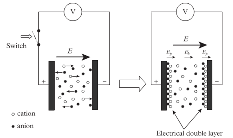
To prevent the effect caused by polarization, EC meters are commonly supplied by AC voltage. By doing so, the ions won’t just move towards one electrode but move back and forth between two electrodes. However, only supplying the AC power cannot fully eliminate the polarization effect. Therefore, when designing the probe of the Multiflexmeter-EC, we had to find another methods to reduce polarization.
Temperature correction
The conductivity of an electrolyte solution increases with temperature. Due to this effect, EC measuring needs temperature correction. A raw EC value needs to be transferred to the value at a reference temperature which is generally 25°C. The conversion formula herefore:
σ25 = σT / (1 + α(T-25))
Where
σ25 = EC value at reference temperature 25°C;
σT = measured (raw) EC value;
T = temperature of measured solution;
α = temperature coefficient.
Measuring principle
The measuring principle of the MFM-EC is based on the 555 timer astable vibrator with 50% duty cycle square wave output. The capacitor’s charging and discharging will generate a square wave. When the output of the 555 timer is HIGH, capacitor C1 will charge through the salt solution between the electrodes. When the output is LOW, it will discharge in opposite direction. The frequency of the output square wave depends on the resistance value between the electrodes.
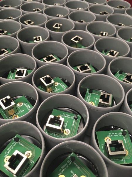
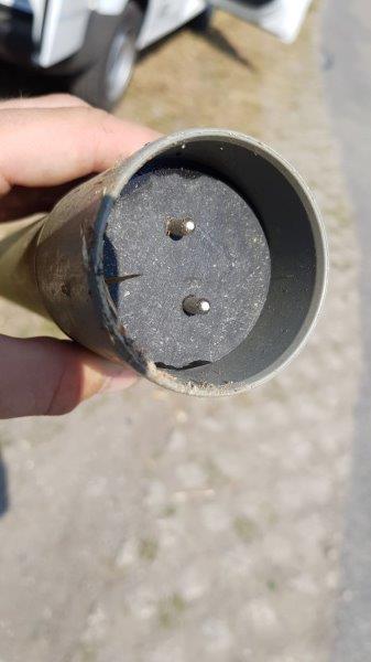
EC-probe
For the probe we choose a common and cheap device containing two nickle plated brass pins:
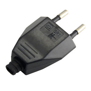
Together with an temperature sensor this plug is connected to a small PCB which fits in a PVC tube. Both electrodes are ligned with an 3D printed disk. The probe has been made waterproof using molding resin.
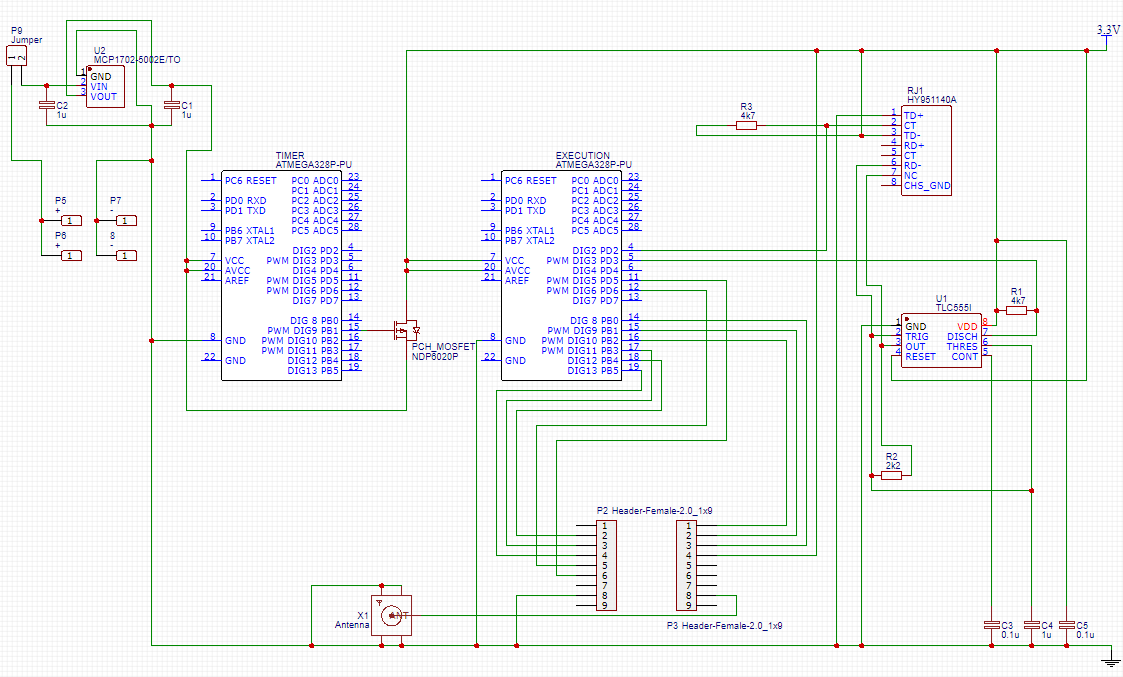
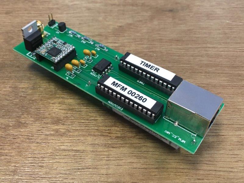
Main circuit
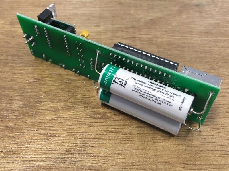
The circuit is built up around two microcontrollers (Atmega 328P, the one used in the Arduino Uno). One acts as a timer, periodically switching the second microcontroller (another Atmega, called ‘Execution’) with a P-channel MOSFET. Every 15 minutes both temperature of the onewire DS18B20 sensor and the frequency generated by the 555 timer is measured and send to the TTN network using a RFM95W 868MHz LoRa module. The system is powered with two parallel placed 3.3V Li-cells (Saft 14500 LS AA). These cells were chosen by their very low self discharge characteristics and their large temperature range.
Components
- TLC555IC
- Rewirable europlug
- DS18B20
- RFM95W LoRa module
- MCP1702-3302E linear regulator
- Saft 14500 LS AA battery (2x)
- P-channel MOSFET NDP6020P
- ATmega328P (2x)
- 3D printed disks (PLA)
Energy consumption
The linear regulator system works like a voltage divider. The current of the input and the output are all the same. But the resistance of the regulator will keep changing to adjust the same output voltage. The output voltage has been measured by a multimeter and the result is exact 3.3V. With the capacity of 2.6Ah, the available power of one battery could be calculated as 8.58Wh. When the device is measuring & sending, the total current in the circuit is 13.1 mA.
A measuring time of 5s appeared to be enough for measuring and sending. After measuring / sending, the system remains at rest for 15 minutes.
During measurement / transmission, the current consumption is 13.1 mA.
Between two measurements the electricity consumption is 7.2 μA.
Power consumption in 1 year: [(13.1mA x 3.3V x 5s) + (7.2μA x 3.3V x 900s)] x 4 x 24 x 365 = 2.31 Wh.
Capacity of two batteries: 17.16Wh
This version of MFM-EC could be used for over 7 years.
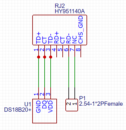
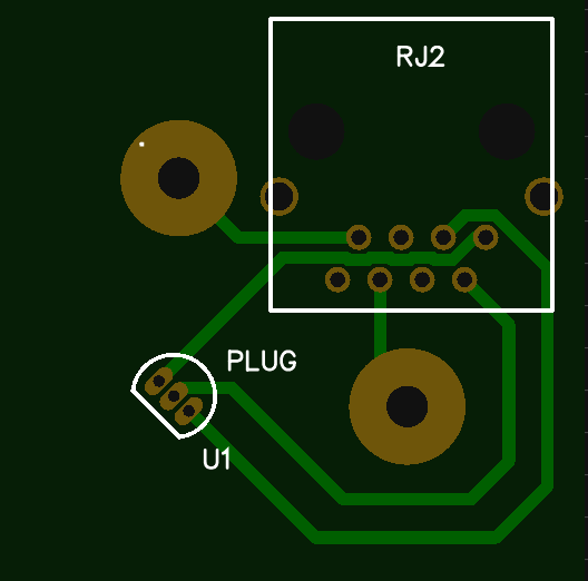
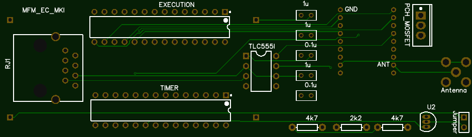
Main PCB
The Multiflexmeter-EC needs two PCB’s: the main PCB with most of the electronics components soldered and the probe PCB with a 3 pin DS18B20 thermo sensor and the 2 electrodes of the plug. Both PCB’s are made using the through hole soldering technique. Both PCBs are interconnected using RJ-connectors and an 8-core UTP cable.
Software
mfm_ec_timer.ino
mfm_ec_transmission.ino
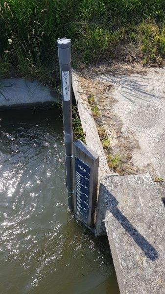
Installation in the field
The EC-probe is fitted at the end of a 40 mm PVC tube. The main PCB is fitted in the tube. The antenna is mounted in the tube at the top cap. Depending on the requested samping depth the complete instrument is screwed to a vertical surface with the probe far enough beneath the water surface.

Data communication
The Ec-meters uses The Things Network (TTN) LoRa-WAN to send the measured 555-frequency and water temperature each 15 minutes to the server.
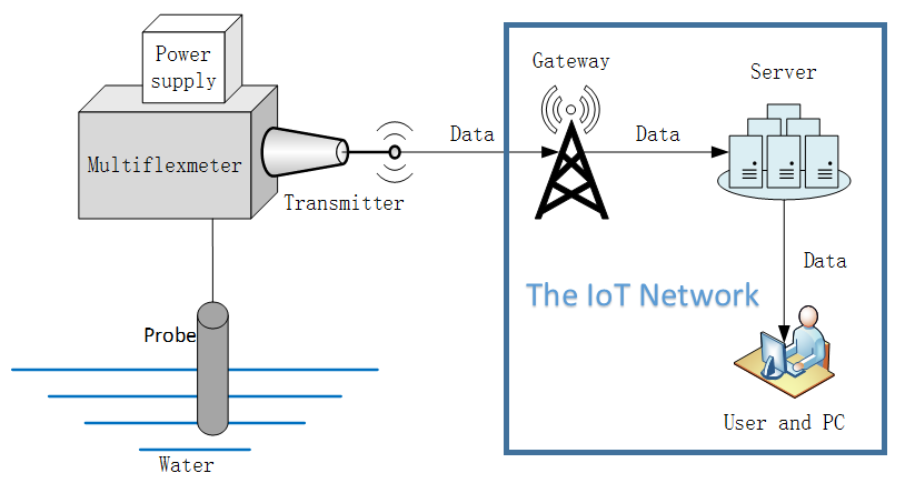
MFM and IoT
In this project a flag pole is used as gateway antenna. The data received from the MFM-EC devices within antenna range is send tot the server using encrypted 4G transmission.

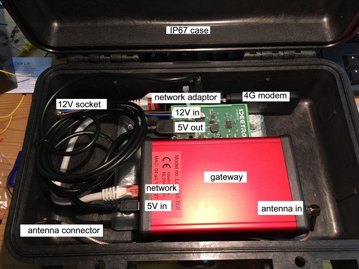
LoRaWan gateway
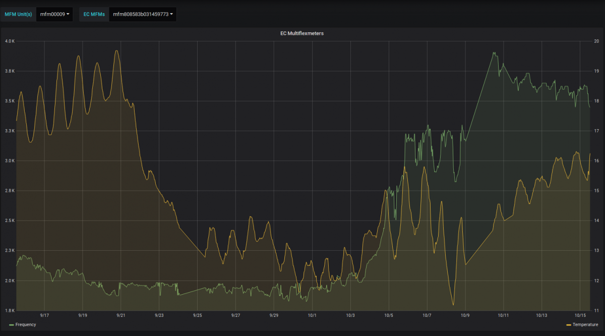
Data presentation tool on the Multiflexmeter server.